Udacity Capstone Design
C++, Python, ROS, Unity
General Info
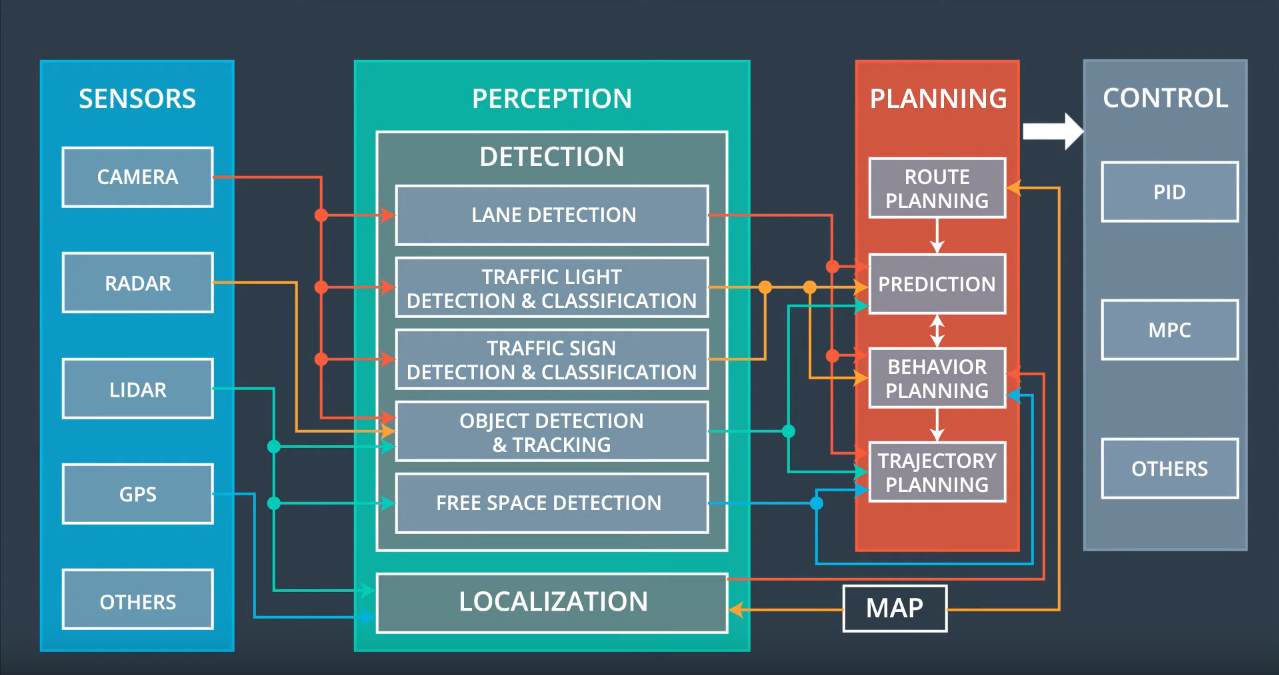
Carla is a self-driving vehicle built by Udacity from a customized Lincoln MKZ. Its self-driving system is divided into four primary components: Sensors, perception, planning, and control are all important parts of the process.
Sensors
Includes everything needed to understand its surroundings and location including cameras, lidar, GPS, radar, and IMU
Perception
Abstracts sensor inputs into object detection and localization
Detection
- Vehicle detection, traffic light detection, obstacle identification, and other software pipelines are included.
- Image processing techniques include feature extraction using the Histogram of Oriented Gradients (HOG), color transforms, and spatial binning.
- For repeated detections, sliding-window or sub-sampling, as well as heat maps and bounding boxes, are used as classification methods.
Localization
- Answers the question: “Where is our car in a given map with an accuracy of 10cm or less?”
- Based on the notion that GPS is not accurate enough
- Onboard sensors are used to estimate transformation between measurements and a given map
Planning
Path planning is broken down into for sub-components: route planning, prediction, behavioral planning, and trajectory planning
Route Planning
The route planning component is in charge of making high-level decisions about how to get a vehicle from one place on a map to another, such as which roads, highways, or freeways to use. This capability is similar to route planning on many smartphones and new car navigation systems.
Prediction
The prediction component forecasts future actions that other objects may take. If another vehicle is detected, for example, the prediction component will calculate its future course.
Behavioral Planning
The behavioral planning component determines the vehicle’s behavior at any given point in time. This component may issue maneuvers such as stopping at a traffic light or intersection, changing lanes, accelerating, or making a left turn onto a new street.
Trajectory Planning
The trajectory planning component will identify which trajectory is appropriate for executing the desired immediate behavior based on the desired immediate behavior.
Control
The control component takes the trajectory outputs and adjusts the control inputs for smooth vehicle operation using a controller algorithm like PID or MPC.
ROS Architecture
Different nodes (written in Python or C++) connect with each other via ROS messages in the ROS Architecture. The nodes are illustrated in the diagram below, along with their communication with one another. The ROS nodes are represented as ovally outlined text boxes inside rectangular boxes, while the topics that are subscribed or published to are represented by simple rectangular boxes. The flow of communication is shown by the direction of the arrows.
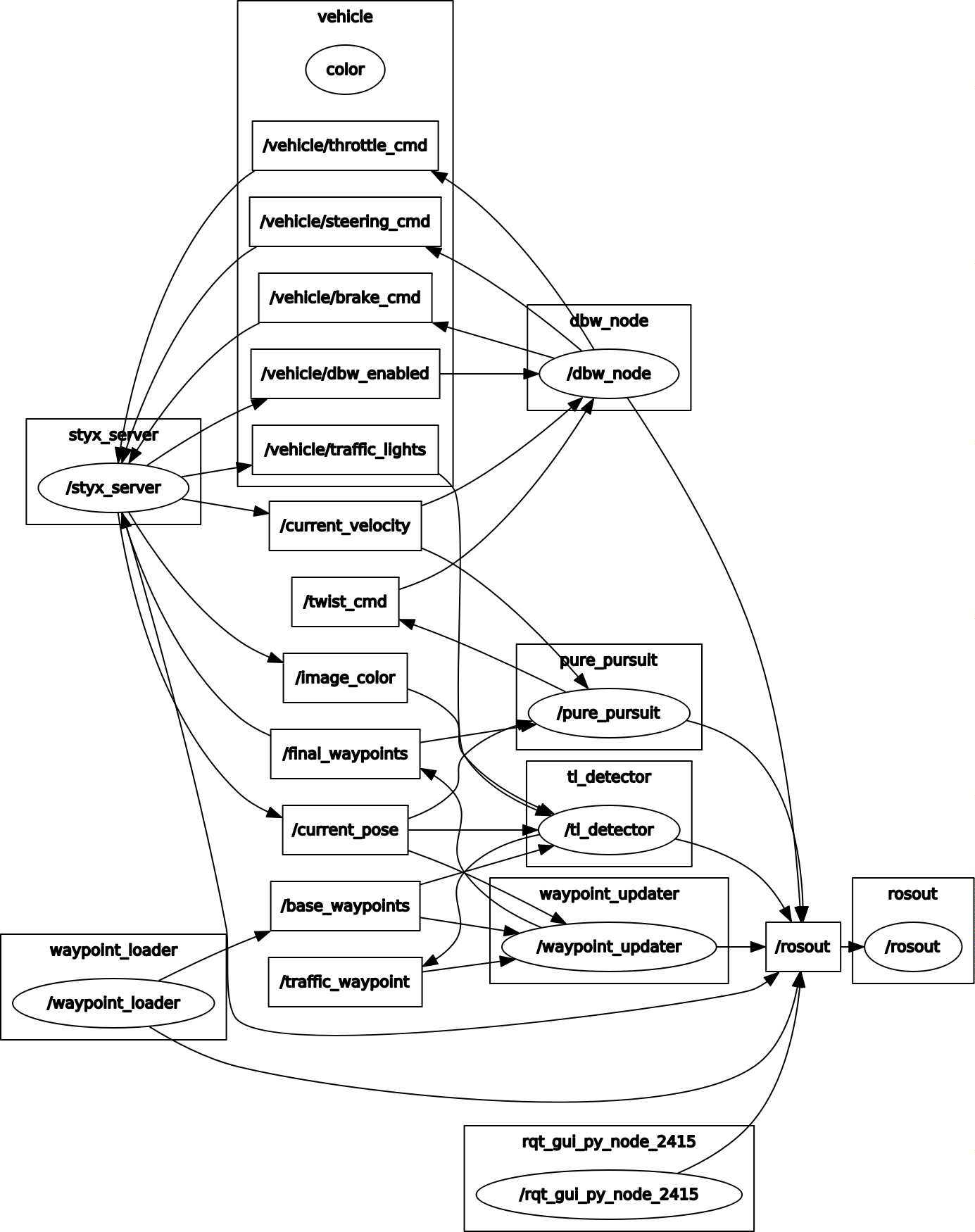
The styx server, which connects the simulator and ROS by delivering information about the car’s condition and surroundings (car’s current position, velocity, and images from the front camera) and accepting control input, is the most central node in the rqt-graph (steering, braking, throttle). The three central tasks of perception, planning, and control are represented by the other nodes.
To recognize traffic lights, the photos are analyzed by a trained neural network within the traffic light classifier. The traffic light detector receives the percepted state of a potentially approaching traffic light, as well as the car’s current pose and a set of base waypoints from the waypoint loader. The traffic light detector can publish a waypoint near the next traffic light where the automobile should stop if the light is red using this often incoming data.
The waypoint updater node can plan acceleration / deceleration and publish it to the waypoint follower node using the traffic light detector’s subscribed information and subscriptions to base waypoints. This node communicates with the DBW (Drive by Wire) node, which handles the duty of autonomously directing the car. It also accepts the current velocity of the automobile (straight from the car / simulator) as an input and outputs steering, braking, and throttle commands.
Node Design

The node design of those nodes that are built within this project will be discussed in this paragraph. Waypoint updater (waypoint updater.py), traffic light detector (tl detector.py), and drive by wire node (dbw node.py) are the three modules.
Waypoint Updater
Because it specifies which waypoints the car should follow, the waypoint updater node plays a crucial role in the planning work. The node is divided into several sections: First, there’s an import section, which imports certain Python libraries and message formats. The initialization of various constants that are not intended to be altered follows. The class WaypointUpdater is introduced after this section. The WaypointUpdater is divided into several sections. The class’s attributes are defined by the init-function, which also determines which topics the class subscribes to and which it publishes on.
The following routines are either generic methods or callback functions that the subscribers in the init-function invoke frequently. The basic waypoints (output of waypoint loader), the car’s posture (simulator / car), and the traffic waypoint (output of tl detector) are all frequently called. The decelerate waypoints-function, which incorporates a square-root shaped deceleration towards a predefined stopline location in the case of red traffic lights, is the most essential general technique. The main function at the end of the node runs the node and logs an error if ROS is halted for any reason.
Traffic Light Detection
The traffic light detector has the same structure as the Waypoint Updater, with an import or startup section followed by a class containing properties and functions. Finally, the TL detection subroutine compiles the code using its main function. The subscriptions to the current location base waypoints, the specified traffic light array containing the ground-truth coordinates of the traffic lights, and the identified color of the traffic light are all included in the TLDetector class’s init-function.
The color of the traffic light is determined by the traffic light classifier, which is a neural network described in greater detail in the following paragraph. The callback image_cb updates the topic image color, which in turn calls the method process traffic lights(), which in turn calls the function get light state(), which receives the traffic light classification. This subroutine eventually publishes the waypoint to halt at for each upcoming detected red traffic signal.
Drive-By-Wire (DBW) Node
The dbw node, which is responsible for driving the car, is the third node that I wrote. It uses a twist controller, which uses a PID-controller and a Lowpass filter to output throttle, brake, and steering values. If dbw_enabled is set to true, the dbw node directly publishes throttle, brake, and steering commands for the car/simulator.
Neural Network Design
Model
The traffic light classification model is based on the pre-trained on the COCO dataset model “faster_rcnn_resnet101_coco” from Tensorflow detection model zoo. Using the Tensorflow Object Detection API, the simulator data model and real data model I trained.
The models are available in the ros/src/tl_detector/light_classification/train_model directory.
Dataset
Step-by-step Tensorflow Object Detection API tutorial was a good guide of using the Tensorflow object detection API for traffic light classification.
The simulator dataset was from here, and the real dataset was from here.
Classification
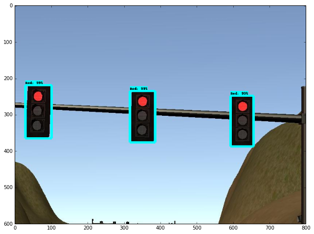
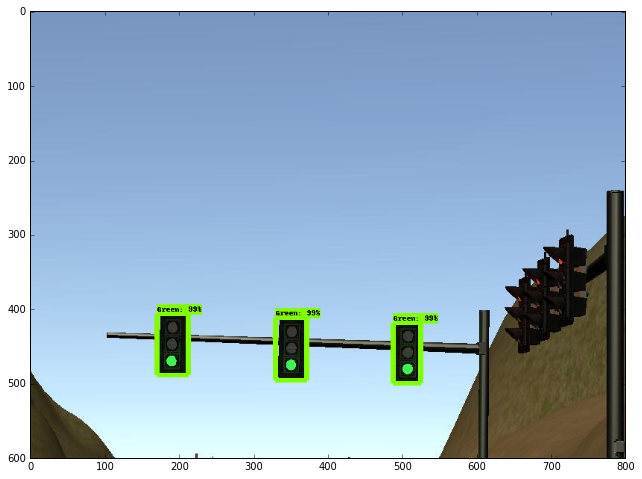
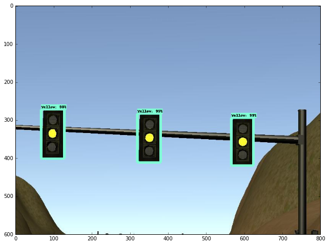
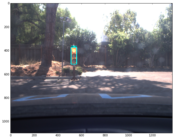
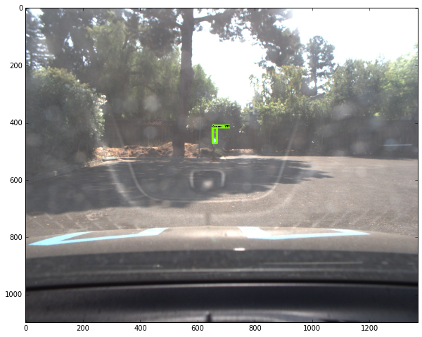
The classification output has four categories: Red, Green, Yellow and off. To simplify, the final output will be Red or Non-Red, that is only the Red will be classified as TrafficLight.RED, and the other cases will be classified as TrafficLight.GREEN.
Output
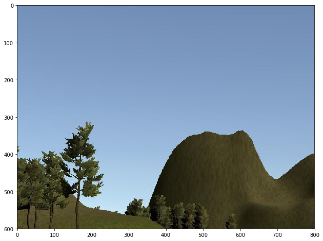
Examples of Simulator Testing Results:
Examples of Real Testing Results:
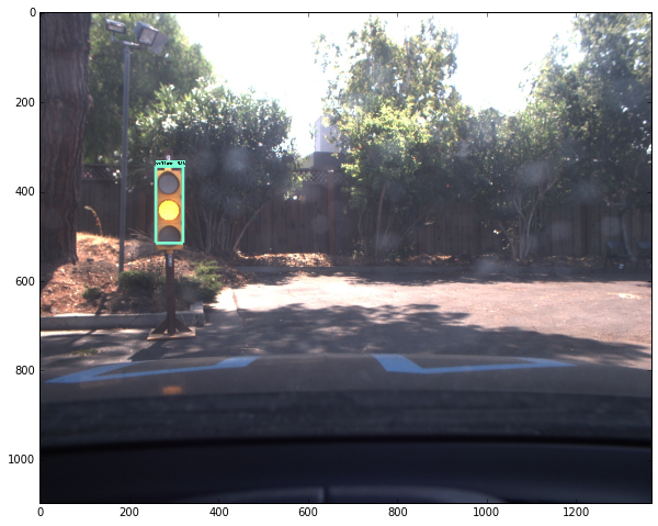
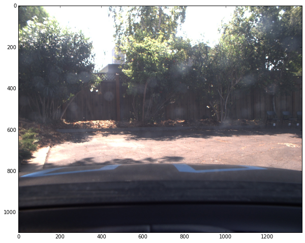
Simulation Result
Following the completion of the program, the walkthrough videos were uploaded to the Udacity project page. There was a rewrite attempt to conform to the walkthrough technique because they had a much more elegant approach to implementing the nodes.
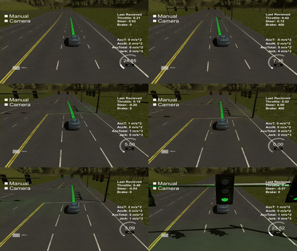
Setting up the environment was one of the most difficult aspects of this project. I misconfigured the Python environment in the VM and was stranded for several hours. After going to the knowledge forum, one of the mentors assisted me greatly in resolving this issue.
In order to accomplish the project, I was also perplexed by how the car should interact and operate within the test lot. For me, the test track is simple to execute because there are basic rules of the road that must be observed in order to effectively travel the track. There are also standardized movements that can be performed on the road that lead to simple vehicle behavior trajectories on the test track. The test lot, on the other hand, is troublesome and peculiar due to the lack of defined road rules and maneuvers to conduct within the test lot.
Another thing I discovered is that while docker setup is much easier, the latency is significantly higher than VM or native setup. As a result, I used VM to run ROS nodes and my native Ubuntu 20.04 LTS to run the simulator for this project.
Overall, this project was both tough and gratifying.